What is the Wiring Assembly Layout of the DC Power Cord for the LS300 and GX Series Modems?
- Jan 13, 2016
- Author: Sierra Wireless
This article provides pinouts and diagrams for the DC power cord used with the LS300 and GX Series modems.
The LS300’s and GX Series power have four pins:
- Two pins connecting DC voltage to the device
- Two pins providing additional monitoring to the device
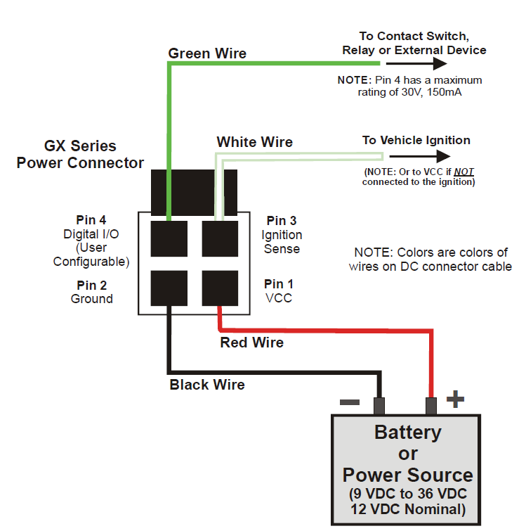
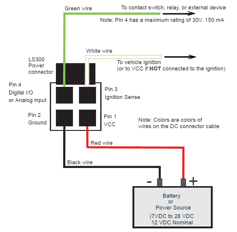
Pin 1 – VCC; Connect to +12VDC (red wire)
Pin 2 – Ground; Connect to ground (black wire)
Pin 3 – The ignition sense pin (white wire). The voltage level present on this pin turns the device on and off. NOTE: If you do not connect this pin to the ignition, you MUST connect it to the positive terminal of your power supply/battery.
Pin 4 – Digital input/output (green wire)
LS300
GX Series